


To make the correct handlebar adjustment for your Polaris AXYS trail, crossover or utility snowmobile, consult the section below that corresponds to your model. For more information, see your Owner’s Manual.
RUSH, SWITCHBACK, XC and TITAN MODELS
The following information applies to:
- RUSH Pro-S and XCR
- Switchback Assault 144, Adventure, SP, Pro-S and XCR
- INDY Adventure, SP, XC, XCR and XD
- TITAN SP, XC and Adventure
- SKS 146
- RMK 144
- Voyageur
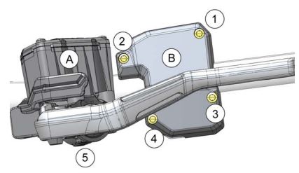
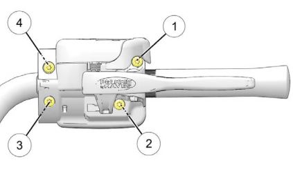
Handlebar Component Fastener Torques
Important: Moving a handlebar component without first loosening its screws/set screws may cut grooves into the handlebar, making it difficult to secure the component. Do not move a handlebar component without first loosening its mounting screws/set screws. Take care to avoid damaging hand warmer/brake switch wires when moving components.
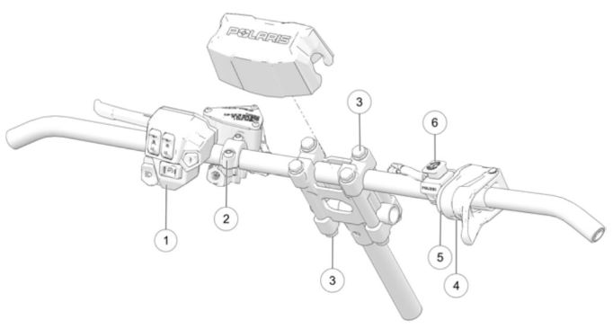
| Item | Description | Torque DO NOT OVER-TIGHTEN |
| 1 | Left Handlebar Control Block | 20 in-lbs (2.3 Nm) |
| 2 | Brake Lever / Master Cylinder Torque the front screw first, and then torque the screw next to the reservoir. | 70 in-lbs (7.9 Nm) |
| 3 | Upper / Lower Riser Clamps | 14.8 ft-lbs (20 Nm) |
| 4 | Throttle Lever Block Set Screw | 27 in-lbs (3.1 Nm) |
| 5 | Throttle Lever Block Cover Screws | 6 in-lbs (0.7 Nm) |
| 6 | Auxiliary Engine Stop Switch Set Screw | 12 in-lbs (1.4 Nm) |
| 7 | Riser | Install with the "FWD" stamp facing toward the hood. |
| Not Shown | Hand Guard Mounts (if applicable) | Hand-Tight |
| Not Shown | Mountain Hoop Bar (if applicable) | 10 ft-lbs (13.6 Nm) |
Handlebar Angle
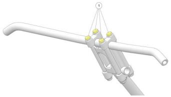
1. Loosen the four bolts on the top riser block (1).
2. Adjust the handlebar upward or downward to the desired angle. Be sure the handlebar, brake lever and throttle lever operate smoothly and do not hit the gas tank, windshield or any other part of the machine when turned fully to the left or right. If necessary, loosen the set screws for the left and right controls, rotate the controls slightly and then tighten the set screws to the proper torque. Do not stretch wires while adjusting the controls. Stretching the wires could damage the handwarmers.
3. Tighten the bolts. Torque to 14.8 ft-lbs (20 Nm).
Riser Angle
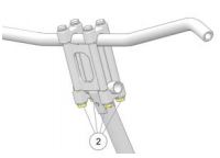
1. Loosen the four bolts on the bottom of the adjuster block (2). If necessary, pry the blocks apart with a screwdriver.
2. Adjust the riser forward or rearward to the desired position.
3. Tighten the bolts. Torque to 14.8 ft-lbs (20 Nm).
Riser Height (If Equipped)
1. Release the riser clamp (1).
2. Adjust the handlebar upward or downward to the desired height.
3. Secure the riser clamp (1).
Periodically inspect the torque of the upper/lower handlebar clamp fasteners and slide fasteners.
| Item | Torque |
| Handlebar Clamp Fastener | 16 ft-lbs (21 Nm) |
| ROX Slide Fastener | 16 ft-lbs (21 Nm) |
| Adjuster Cranks | Hand-Tight |
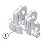
Left Hand Control Alignment
Important: Moving the left hand control without loosening the four mounting screws will cause the housing locating pins to cut grooves into the handlebar. When this occurs, the left hand control may not clamp tightly to the handlebar. If the left hand control was inadvertently moved without loosening the screws and is loose, loosen the mounting screws and move the control block slightly to the left or right to relocate the pins. Torque the screws to specification.
1. Loosen the brake master cylinder (A) mounting screws and move it away from the left hand control (B). Take care to avoid damaging hand warmer/brake switch wires when moving components.
2. Loosen the four left hand control mounting screws.
3. Move the control block to the desired position.
4. Tighten the screws to specification in the sequence shown in the image above. Do not over-torque. Torque to either 24 in-lbs (2.7 Nm) or 20 in-lbs (2.3 Nm), depending on your model. See your Owner’s Manual for the proper specification.
5. Return the master cylinder to its specified position. Make sure the clamp does not pinch the brake light signal wire. Torque the clamp screws to 70 in-lbs (7.9 Nm), beginning with the front screw first and then the screw next to the reservoir. Do not over-torque.
Handlebar Component Locations
Refer to the following illustrations and measurements to position handlebar components at factory-specified locations. Notice: Do not move handlebar components without first loosening the components' screws.
For Switchback Assault 144, SKS, RMK, Voyageur, RUSH XCR and INDY models:
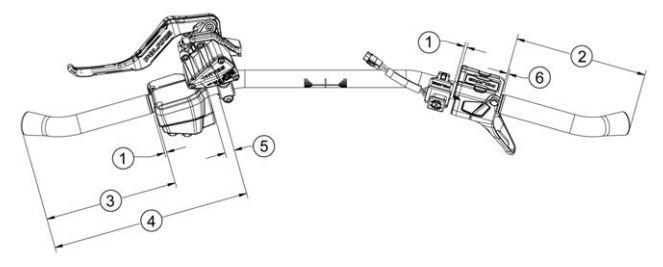
| Item | Measurement |
| 1 | 0.011 in (3 mm) |
| 2 | 6.65 in (169 mm) |
| 3 | 6.7 in (170 mm) |
| 4 | 10 in (254 mm) |
| 5 | 0.47 in (12 mm) |
| 6 | 0.08 in (2 mm) |
For TITAN, Switchback Pro-S, Switchback XCR and RUSH Pro-S models:
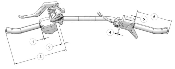
| Item | Measurement |
| 1 | 0.039 in (1 mm) |
| 2 | 0.51 in (13 mm) |
| 3 | 10 in (254 mm) |
| 4 | 0.13 in (3.3 mm) |
| 5 | 0.08 in (2 mm) |
| 6 | 6.65 in (169 mm) |
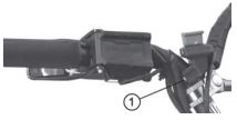
Throttle Block Alignment

1. Slightly loosen the set screw (1) on the bottom of the housing.
2. Move the control block to the desired position.
3. Torque the screw to 27 in-lbs (3 Nm). Do not over-torque.
Engine Stop Switch Alignment
Caution: The stop switch must be positioned in an easily accessible location.
1. Slightly loosen the set screw on the bottom of the housing (1).
2. Move the switch to the desired position.
3. Torque the screw to 12 in-lbs (1.4 Nm). Do not over-torque.
550 AND 600 INDY MODELS
The following information applies to:
- 550 INDY 121, 144, LXT and Adventure
- 550 Voyageur
- 600 INDY
- INDY EVO and INDY EVO RMK
- WIDETRAK LX
To find handlebar component fastener torques for your vehicle, consult your Owner’s Manual. Note that moving a handlebar component without first loosening its screws/set screws may cut grooves into the handlebar, making it difficult to secure the component. Do not move a handlebar component without first loosening its mounting screws/set screws. Take care to avoid damaging hand warmer/brake switch wires when moving components.
Left Hand Control Alignment
1. Loosen the four control block mounting screws.
2. Move the control block to the desired position. If the control is loose and was inadvertently moved without loosening the screws, move the control block slightly to the left or right to relocated the pins.
3. Tighten the screws to specification in the sequence shown in the image above. Torque to 24 in-lbs (2.7 Nm). Do not over-torque.
Throttle Block Alignment
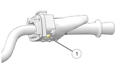
1. Slightly loosen the set screw (1) on the bottom of the housing.
2. Move the control block to the desired position.
3. Tighten the screw to specification. Do not over-torque. Torque to the specification in your Owner’s Manual, either 35 in-lbs (4 Nm) or 27 in-lbs (3 Nm), depending on your model.
4. With the engine off, test throttle lever movement after tightening the screw.
Engine Stop Switch Alignment (600 INDY)
1. Slightly loosen the set screw on the bottom of the housing.
2. Move the switch to the desired position. The stop switch must be positioned in an easily accessible location.
3. Torque the screw to 12 in-lbs (1.4 Nm). Do not over-torque.
Handlebar Angle or Position
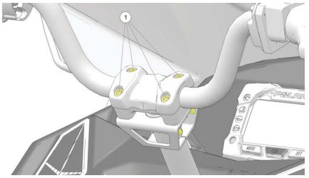
1. Securing the handlebar clamp bolts (1) with an Allen wrench, loosen each of the four nuts (located on each bolt’s opposite end). Take care to avoid damaging hand warmer/brake switch wires when moving components.
2. Adjust the handlebar forward or rearward to the desired angle.
3. Be sure the handlebar, brake lever and throttle lever operate smoothly and do not hit the gas tank, windshield or any other part of the machine when turned fully to the left or right. If necessary, adjust the left and right hand controls.
4. Tighten the handlebar clamp nuts to the specification in your Owner’s Manual. This will vary based on model. Do not over-torque.
For more information, see your authorized Polaris Dealer. To find a dealer near you, use the Dealer Locator.
Maintenance tips, procedures and specifications can be found in your Owner’s Manual.
To find diagrams and replacement part numbers, use the online parts catalog.
Unless noted, trademarks are the property of Polaris Industries, Inc.
© 2022 Polaris Industries Inc.


