


The following information applies to the Polaris AXYS platform mountain and deep snow snowmobiles listed below.
- PRO-RMK
- SKS 155
- RMK Assault
- RMK KHAOS
Handlebar Component Fastener Torques
Important: Moving a handlebar component without first loosening its screws/set screws may cut grooves into the handlebar, making it difficult to secure the component. Do not move a handlebar component without first loosening its mounting screws/set screws. Take care to avoid damaging hand warmer/brake switch wires when moving components.
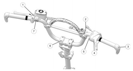
| Item | Description | Torque DO NO OVER-TIGHTEN |
| 1 | Brake Lever / Master Cylinder | 60-80 in-lbs (6.7-9 Nm) |
| 2 | Auxiliary Engine Stop Switch Set Screw | 12 in-lbs (1.4 Nm) |
| 3 | Handlebar Hook Screw | Aluminum: 10 ft-lbs (13.5 Nm) Steel: 18 ft-lbs (24 Nm) |
| 4 | Throttle Lever Block Set Screw | 27 in-lbs (3 Nm) |
| 5 | Throttle Lever Block Cover Screws | 6 in-lbs (0.7 Nm) |
| 6 | Handlebar Clamp Screws/Bolts | 35 in-lbs (4 Nm) |
| 7 | PERC Button Screw | 35 in-lbs (4 Nm) |
Cyclone Brake Master Cylinder Alignment
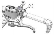
1. Loosen the two mounting screws. Take care to avoid damaging hand warmer/brake switch wires when moving components.
2. Move the master cylinder to the desired position.
3. Torque the screws to specification, which is 60-80 in-lbs (6.7-9 Nm). Torque the front screw (1) first and then torque the screw (2) next to the reservoir. Do not over-torque.
Throttle Block Alignment
Take care to avoid damaging hand warmer wires when moving components.
1. Slightly loosen the set screw (1) on the bottom of the housing.
2. Move the control block to the desired position.
3. Torque the screw to specification, which is 27 in-lbs (3 Nm). Do not over-torque.
4. With the engine off, test throttle lever movement after tightening the screw.
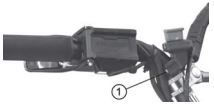
PERC Button Alignment
1. Loosen the mounting screw (1).
2. Move the PERC button to the desired position.
3. Torque the screw to 35 in-lbs (4 Nm). Do not over-torque.
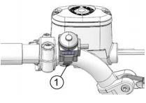
Engine Stop Switch Alignment
1. Slightly loosen the set screw (1) on the bottom of the housing.
2. Move the switch to the desired position.
3. Torque the screw to 12 in-lbs (1.4 Nm). Do not over-torque.
Caution: The stop switch must be positioned in an easily accessible location.
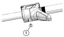
Handlebar Hook Alignment
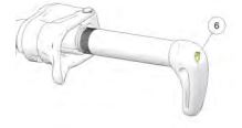
1. Slightly loosen the clamping screw (1). Do not remove the screw.
2. Rotate the hook to the desired position.
3. Torque the screws on aluminum bars to 10 ft-lbs (13.5 Nm) and the screws on steel bars to 18 ft-lbs (24 Nm). Do not over-torque.
Handlebar Angle Adjustment
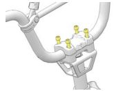
1. Securing the handlebar clamp bolts with an Allen wrench, loosen each of the four nuts. Take care to avoid damaging hand warmer/brake switch wires when moving components.
2. Adjust the handlebar forward or rearward to the desired angle.
3. Be sure the handlebar, brake lever and throttle lever operate smoothly and do not hit the gas tank, windshield or any other part of the machine when turned fully to the left or right. If necessary, adjust the left and right hand controls.
4. Tighten the handlebar clamp nuts. Torque to 35 in-lbs (4 Nm). Do not over-torque.
For more information, see your authorized Polaris Dealer. To find a dealer near you, use the Dealer Locator.
Maintenance tips, procedures and specifications can be found in your Owner's Manual.
To find diagrams and replacement part numbers, use the online parts catalog.
Unless noted, trademarks are the property of Polaris Industries Inc.
© 2022 Polaris Industries Inc.


