


The following are overviews of gauges and instrument clusters found on Polaris snowmobiles not equipped with a Polaris Interactive Digital Display (PIDD) or 7S display. Some features will vary from model to model.
Ten-Icon Digital Gauge
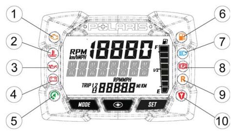
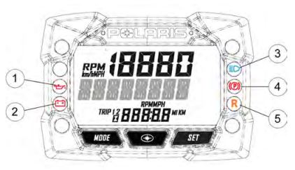
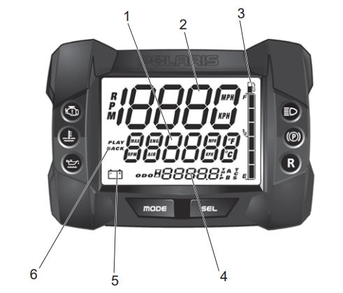
The instrument cluster contains the Rider Information Center and the following indicator lights: Check Engine (1), Engine Hot (2), Low Oil (3), Low Battery Voltage (4), Playback (5), Low Fuel (6), High Beam (7), Parking Brake (8), Reverse (9) and Security (10).
| Indicator | Condition |
 | This indicator appears if an EFI-related fault occurs. Do not operate the snowmobile if this warning appears. Serious engine damage could result. Your Polaris Dealer can assist. |
 | The over-temperature indicator will illuminate when the engine is overheating. Take action to cool to engine. The indicator will flash when engine temperature reaches critical levels. Stop the engine immediately. |
 | The low oil indicator light may flicker at times due to oil movement in the bottle, but when the light comes on and remains on, add the recommended oil before further operation. |
 | The low battery voltage indicator illuminates when the battery voltage is low. |
 | The playback indicator illuminates when the gauge is in playback mode. |
 | The low fuel indicator illuminates when fuel is low. |
 | The high beam indicator illuminates when the lights are set to high beam. |
 | The parking brake indicator illuminates when the parking brake is engaged. It also will illuminate when the service brake is in use. |
 | The reverse indicator flashes when the transmission is in reverse. |
 | The security indicator illuminates when the security system is activated. Read Polaris Snowmobile Security System for more information. |
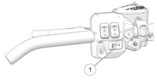
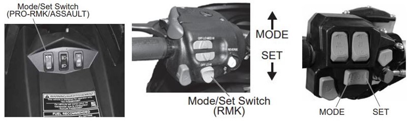
On Matryx models, the Rider Information Center can be controlled by the Arrow buttons (11) and SELECT button (12) on the left hand controls, as shown below.
On AXYS models, the Rider Information Center can be controlled by either the MODE and SELECT buttons on the instrument cluster or by using the MODE/SET switch on the Left Hand Control, as shown below.
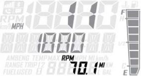
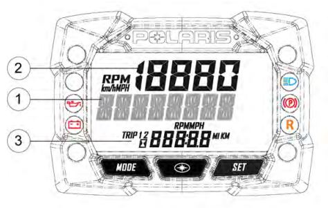
The Rider Information Center is located in the instrument cluster. The center displays vehicle speed, engine speed, odometer, resettable trip meters (2), total engine hours of operation, fuel level, engine temperature and diagnostic display mode.
Setting changes must be made with the engine running or with the vehicle powered by an external DC power supply connector. The information center is set to display standard units of measurement for distance and temperature.
(1) Information Display Area: This area displays either engine speed or vehicle speed (whichever is not displayed in the speed display), engine temperature, maximum vehicle speed, and speed or revolutions per minute (RPM). To change the display, press and release the MODE button or the MODE switch until the desired item is displayed.
(2) Speed Display: The speed display area displays either vehicle speed or engine speed. Vehicle speed is displayed in either miles per hour (mph) or kilometers per hour (km/h). Engine speed is displayed in RPM. To change which item displays, first make sure the information display area is set to display either engine speed or vehicle speed. Press and release the center  button.
(3) Fuel Gauge: Not available on all models. The segments of the fuel gauge show the level of fuel in the fuel tank. When the last segment clears, a low fuel warning is activated. All segements, including the fuel icon, will flash. Refuel immediately. Note: The low fuel indicator and fuel level gauge on the Standard Instrument Cluster are not supported on models with a fuel level gauge on the fuel cap.
If the fuel icon fails to display, an open cap or short circuit has occurred in the fuel sensor circuit. See your Polaris Dealer.
(4) Odometer/Engine Hour Display: This area displays the odometer, Trip 1 meter, Trip 2 meter, clock and engine hours meter.
The odometer displays the total distance traveled by the vehicle since manufacture. Each trip meter records the distance traveled by the vehicle on a trip if the meter is reset before each trip. The clock displays the time, and the engine hour meter displays the total hours the engine has been in operation since manufacture.
To change the display, press and release the SET button or SET switch until the desired item is displayed.
To reset a trip meter, press and hold the SET button or SET switch until the meter resets to zero.
Read Setting the Clock on Your Snowmobile for more information on the clock.
The odometer and temperature displays can be viewed in either standard or metric units of measurement. Both displays change if units are changed. The new settings will remain until changed by the operator. There are two methods of changing the display.
The first method is:
1. Press and hold the center button on the instrument cluster to enter the Options Menu.
2. Press and release the MODE button until engine temperature appears in the Information Display Area.
3. Press and release the SET button or SET switch to change units.
The second method is:
1. Press and release the SET button or SET switch until the odometer appears in the Information Display Area.
2. Press and hold the SET button or SET switch until the units change.
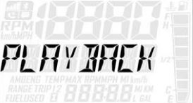
Playback function: The playback function allows the rider to record and play back engine speed, vehicle speed and throttle position sensor information for up to 3 minutes.
To record:
1. Press and hold the center button on the instrument cluster to enter the Options Menu.
2. Press and release the MODE button until PLAYBACK appears in the information display area.
3. Press and release the SET button. RECORD will appear in the information display area.
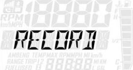
4. To begin recording, press and release the SET button. The playback indicator will flash while the recording is in progress. Recording is complete when the light stops flashing. To stop recording at any time during the recording process, press and release the SET button.
To play back the recorded data:
1. Stop the vehicle and and wait for engine speed to drop below clutch engagement.
2. Press and hold the center button on the instrument cluster to enter the Options Menu.
3. Press and release the MODE button until PLAYBACK appears in the information display area.
4. Press and release the SET button twice. PLAY will appear in the information display area.
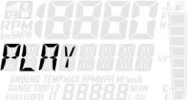
5. Press and release the SET button to play the recorded data. Once playback has concluded, REPLAY will appear in the Information Display Area.
6. Press and release the SET button to replay recorded data.
7. Press and release the MODE button to end playback and return to the Options Menu.
Diagnostic display mode: The diagnostic display mode is for informational purposes only. Your Polaris Dealer can perform all major repairs.
The diagnostic mode is accessible only when the check engine warning indicator is illuminated and a diagnostic code is active.
Do not stop the engine if you want to view the active code (failure code). Active codes cannot be retrieved if power is interrupted to the instrument cluster. The codes will become inactive codes if power is interrupted. Inactive codes are stored in the history of the unit. Your Polaris Dealer can help retrieve inactive codes.
Use the following procedure to view active codes:
1. Do not stop the engine.
2. Press and hold the center button on the instrument cluster to enter the Options Menu.
3. Press and release the MODE button until DIAGCODE appears in the Information Display Area. The diagnostic display mode will appear in the Options Menu if there is an active trouble code.
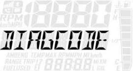
When the diagnostic code mode is displayed, the check engine warning indicator will begin to flash.
4. A set of two numbers will appear in the display.
- The 2-6 digit suspect parameter number (SPN) in the information display area indicates which component is generating the fault code.
- The 1-2 digit failure mode indicator (FMI) number in the odometer area indicates the fault mode, such as open or short circuit.
5. More than one fault may be active. Press and hold the SET button or SET switch for 2 seconds to toggle to the next active code. Repeat until all codes are retrieved.
6. See the Diagnostic Display Code Definition section in your Owner's Manual for code definitions and failure descriptions.
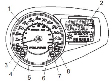
Five-Icon Digital Gauge
Some models have standard instrument clusters featuring five icons: Low Oil (1), Low Battery Voltage (2), High Beam (3), Parking Brake (4) and Reverse (5).
| Indicator | Condition |
| The low oil indicator light may flicker at times due to oil movement in the bottle, but when the light comes on and remains on, add the recommended oil before further operation. |
| The low battery voltage indicator illuminates when the battery voltage is low. |
| The high beam indicator illuminates when the lights are set to high beam. |
| The parking brake indicator illuminates when the parking brake is engaged. It also will illuminate when the service brake is in use. |
| The reverse indicator flashes when the vehicle is in reverse. Slow flash for low elevation. Fast flash for high elevation (above 6,000 feet). To change from low to high speed, hold the reverse button for 5 seconds. |
The rider information center is located in the instrument cluster. The center displays vehicle speed, engine speed, odometer, resettable trip meters (2), total engine hours of operation, fuel level, engine temperature and diagnostic display mode.
Setting changes must be made with the engine running or with the vehicle powered by an external DC power supply connector. The information center is set to display standard units of measurement for distance and temperature.
(1) Information Display Area: This area displays either engine speed or vehicle speed (whichever is not displayed in the speed display), maximum vehicle speed, and speed or revolutions per minute (RPM). To change the display, press and release the MODE button or the MODE switch until the desired item is displayed.
(2) Speed Display: The speed display area displays either vehicle speed or engine speed. Vehicle speed is displayed in either miles per hour (mph) or kilometers per hour (km/h). Engine speed is displayed in RPM.
To change which item displays, first make sure the information display area is set to display either engine speed or vehicle speed. Press and release the center button.
(3) Odometer/Engine Hour Display: This area displays the odometer, Trip 1 meter, Trip 2 meter, CLOCK and engine hours meter.
The odometer displays the total distance traveled by the vehicle since manufacture. Each trip meter records the distance traveled by the vehicle on a trip if the meter is reset before each trip. The CLOCK displays the time, and the engine hour meter displays the total hours the engine has been in operation since manufacture.
To change the display, press and release the SET button or SET switch until the desired item is displayed.
To reset a trip meter, press and hold the SET button or SET switch until the meter resets to zero.
Read Setting the Clock on Your Snowmobile for more information on the clock.
Six-Icon Digital Display
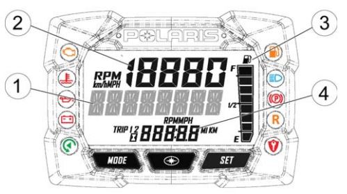
The instrument cluster contains indicator lights and the Rider Information Center.
The check engine indicator appears if an EFI-related fault occurs. Do not operate the snowmobile if this warning appears. Serious engine damage could result. See your Polaris Dealer.
The over-temperature indicator illuminates to alert the operator that the engine is overheating. The operator should take action to cool the engine. See your Owner's Manual for more information. If the indicator flashes, continued operation could result in serious engine damage. Stop the engine immediately.
The low oil indicator light may flicker at times due to oil movement in the bottle. But when the light comes on and remains on, add the recommended oil before further operation. See your Owner's Manual for oil recommendations.
The high beam indicator illuminates when the lights are set to high beam.
The parking brake indicator illuminates when the parking brake is engaged. It also will illuminate when the service brake is in use.
The reverse indicator flashes when the transmission is in reverse.
The information center can be controlled by either the MODE or SELECT buttons on the instrument cluster or by the MODE/SET switch on the left handlebar or console.
The Rider Information Center is located in the instrument cluster. It displays vehicle speed, engine speed, odometer, two resettable trip meters, total engine hours of operation, fuel level, engine temperature and diagnostic display mode.
Setting changes must be made with the engine running or with the vehicle powered by an external DC power supply connector.
The information center is set to display standard units of measurement for distance and temperature. See below for directions on changing the display to metric units.
Making up the Rider Information Center are:
The Information Display Area (1), which displays either engine speed or vehicle speed (whichever is not displayed in the speed display), engine temperature and maximum vehicle speed. To change the display, press and release the MODE button or the MODE switch until the desired item is displayed.
The Speed Display (2) area displays either vehicle speed or engine speed. Vehicle speed is displayed in either miles per hour (mph) or kilometers per hour (km/h). Engine speed is displayed in revolutions per minute (RPM).
To change which item displays, first make sure the Information Display Area is set to display either engine speed or vehicle speed. Then press and hold the mode button (on the instrument cluster) or the mode switch (on the left handlebar) for 3 seconds.
The Fuel Gauge (3) contains segments, which show the level of fuel in the fuel tank. When the last segment clears, a low fuel warning is activated. All segments, including the fuel icon, will flash. Refuel immediately. If the fuel icon fails to display, an open or short circuit has occurred in the fuel sensor circuit. See your Polaris Dealer.
The Odometer/Engine Hour Display (4) shows the odometer, Trip A, Trip B and engine hours. The odometer displays the total distance traveled by the vehicle since manufacture. each trip meter records the distance traveled by the vehicle on a trip if the meter is reset before each trip. The engine hour meter displays the total hours the engine has been in operation since manufacture.
To change the display, press and release the SELECT button or the SET switch until the desired item is displayed. To reset a trip meter, press and hold the SELECT button or the SET switch until the meter resets to zero.
The Battery Power (5) indicator illuminates when battery power is low.
The Playback Icon (6) is for the playback function, which allows the rider to record and play back engine speed, vehicle speed and throttle position sensor information for up to 3 minutes.
To begin recording, simultaneously press and hold the MODE and SELECT buttons on the instrument cluster for 3 seconds. The playback indicator will flash while the instrument cluster is recording.
To play back the recorded data, stop the vehicle and wait for engine speed to drop below clutch engagement.
Simultaneously press and release the MODE and SELECT buttons on the instrument cluster.
Applying the throttle will clear the display and return the instrument cluster to normal operation.
The odometer and temperature displays can be viewed in either standard or metric units of measurement. Both displays change if units are changed. The new settings will remain until changed by the operator. There are two ways to change between standard and metric:
1. Press and release the MODE button or MODE switch until engine temperature displays. Press and hold the MODE button or MODE switch until the units change.
2. Press and release the SELECT button or SET switch until the odometer displays. Press and hold the SELECT button or SET switch until the units change.
Diagnostic display mode: The diagnostic display mode is for informational purposes only. Your Polaris Dealer can perform all major repairs.
The diagnostic mode is accessible only when the check engine warning indicator is illuminated and a diagnostic code is active.
Do not stop the engine if you want to view the active code (failure code). Active codes cannot be retrieved if power is interrupted to the instrument cluster. The codes will become inactive codes if power is interrupted. Inactive codes are stored in the history of the unit. Your Polaris Dealer can help retrieve inactive codes.
Use the following procedure to view active codes:
1. Do not stop the engine.
2. With the brake engaged, press and release the SELECT button or SET switch to toggle to the diagnostic display mode. When a code is active, the diagnostic display mode will appear immediately following the engine hour display. When the diagnostic mode is displayed, the check engine warning indicator will begin to flash.
3. A set of two numbers will appear in the display.
- The 2-6 digit suspect parameter number (SPN) in the information display area indicates which component is generating the fault code.
- The 1-2 digit failure mode indicator (FMI) number in the odometer area indicates the fault mode, such as open or short circuit.
4. More than one fault may be active. Press and hold the SET button or SET switch for 2 seconds to toggle to the next active code. Repeat until all codes are retrieved.
5. See the Diagnostic Display Code Definition section in your Owner's Manual for code definitions and failure descriptions.
Standard Round Gauge
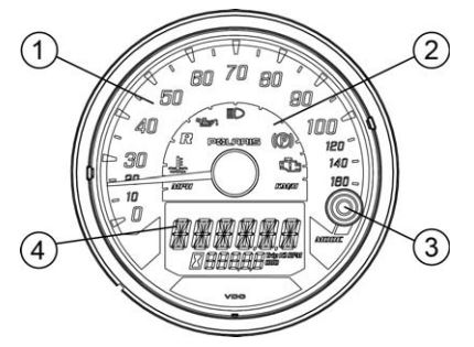
This instrument cluster contains the speedometer (1), indicator lamps (2), MODE button (3) and Rider Information Center (4).
The speedometer displays vehicle speed in either mph or km/h.
The following indicator lamps are included:
| Lamp | Indicates | Condition |
 | Vehicle Speed | When standard mode is selected, speed displays in miles per hour. When metric mode is selected, speed displays in kilometers per hour. |
 | Reverse | This indicator flashes when the transmission is in reverse. See your Owner's Manual for more. |
 | High Beam | The high beam indicator illuminates when the lights are set to high beam. |
 | Parking Brake | This indicator illuminates when the parking brake is engaged. It also will illuminate when the service brake is in use. See your Owner's Manual for more. |
 | Low Oil | The low oil indicator light may flicker at times due to oil movement in the bottle, but when the light comes on and remains on while at idle, add the recommended oil before further operation. See your Owner's Manual for more. |
The Rider Information Center is controlled by the MODE button (1) on the instrument cluster. Use the MODE button to toggle through the available modes. Setting changes must be made with the engine running or with the vehicle powered by an external DC power supply connector. On some models, changes are saved by using the SET switch found on the handlebar.
The information center is set to display standard units of measurement at the factory.
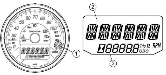
The Information Display Area (2) displays either engine speed, engine temperature or maximum vehicle speed.
The Odometer/Engine Hour Display Area (3) displays the odometer, trip meters and engine hours.
The display can be changed to display either standard or metric units of measurement. While in the engine temperature display, press and hold the MODE button to change units.
| Standard Display | Metric Display | |
| Distance | Miles | Kilometers |
| Temperature | Fahrenheit | Celsius |
The odometer records and displays the distance traveled by the vehicle.
The trip meter records the distance traveled by the vehicle if reset before each trip. To reset, select the trip meter mode. Press and hold the MODE button until the meter resets to zero. In the Rider Information Center, the trip meter display contains a decimal point, but the odometer displays without a decimal point.
The hour meter mode logs the total hours the engine has been in operation.
The tachometer mode displays the engine RPM digitally. Small fluctuations in the RPM from day to day may be normal because of changes in humidity, temperature and elevation.
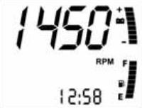
Multi-Function Display
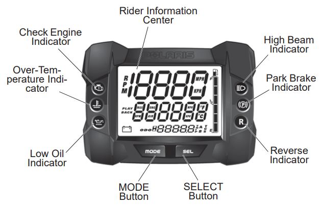
The Multi-Function Display is made up of the analog gauge (1), digital gauge (2), check engine indicator (3), low oil indicator (4), high temp indicator (5), brake indicator (6), reverse indicator (7) and high beam indicator (8).
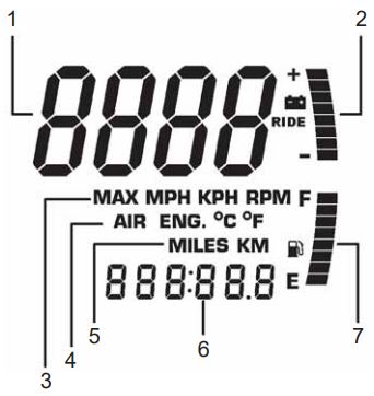
Within the digital gauge the following information can be found:
| Item | Function |
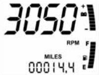
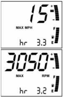
| 1 | RPM or Speed Altitude (if equipped) Service Interval |
| 2 | Electrical System Voltage Level |
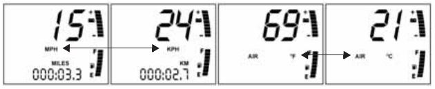
| 3 | MAX - Maximum MPH/KPH or RPM MPH - Miles per hour KPH - Kilometers per hour RPM - Engine crankshaft revolutions per minute |
| 4 | Air Temp (if equipped) Engine Temp Degrees Celsius Degrees Fahrenheit |
| 5 | Miles Kilometers |
| 6 | Hours Trip 1/Trip 2/Trip F Service Label Altitude Label |
| 7 | Fuel Level (if equipped) |
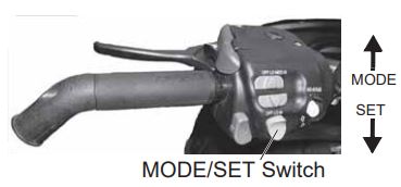
The Multi-Function Display control switch allows you to set the MFD display to your preferences. The rocker switch has a MODE button (top) and a SET button (bottom). Specific instructions are outlined on the following pages.
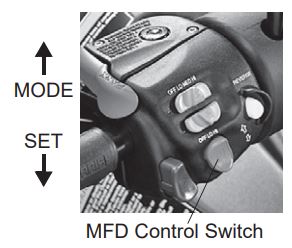
The MFD will display either standard or metric units of measurement. While viewing a screen that displays measurements (mph, km/h or temperatures), press and hold the MODE switch until the unit of measurement changes (about 10 seconds).
The speedometer and tachometer can be viewed in either the analog or the digital display. If the analog display is set to show speedometer readings, the digital screen automatically will display the tachometer (option 1). If the analog is set to show the tachometer, the digital screen will show the speedometer (option 2).
To change viewing preferences, press and hold the MODE button for 3 seconds. When the button is released, the new settings becomes active and screen colors change. See the below table.
| Option | Analog Display | Digital Display | Analog Screen | Digital Screen |
| 1 | Speed | RPM | Blue MPH | Blue Backlight |
| 2 | RPM | Speed | Red X100RPM | Red Backlight |
Press and release the MODE button to cycle through the three MFD programs: Performance, Engine and History. Each program remains active until you cycle to the next program. While any program is active, press and release the SET button to cycle through the program's screens.
The Performance Program automatically displays either speed or tachometer, whichever is opposite the analog display. It also displays electrical system voltage and fuel level (if equipped).
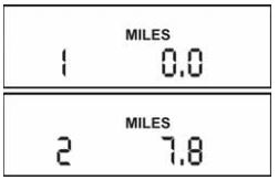
While in the Performance mode, press the SET button to cycle through the odometer, Trip 1, Trip 2, Trip F (if equipped with electronic fuel gauge) and Clock (if equipped). Use the following procedures to make changes to these screens.
The odometer records the vehicle's total distance traveled since manufacture. The odometer cannot be reset.
Trip 1 and Trip 2 are odometers used to check mileage or to keep track of distance traveled. Both odometers can be reset to zero. To reset an odometer:
1. Enter the Performance Program.
2. Press and release the SET button until the desired trip screen is active.
3. Press and hold the SET button for 2 seconds to reset the trip odometer to zero.
4. Press and release the SET button to cycle through additional screens.
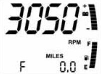
If the snowmobile is equipped with an electronic fuel gauge, Trip F automatically displays when the fuel level is low. The fuel symbol and the last fuel bar on the MFD gauge will blink when the fuel level reaches 1/8 of a tank.
The Trip F odometer records distance traveled until enough fuel is added to raise the level above 1/4 tank. The fuel symbol and the fuel bar will continue to blink until the fuel level is above 1/4 tank. The Trip F odometer automatically will reset to zero after refueling.
To change the clock setting:
1. Enter the Performance Program.
2. Press and release the SET button until the clock screen is active.
3. Press and hold the SET button for 5 seconds.
4. When the hour starts flashing, press the SET switch once to advance one hour (press and hold the SET button to advance the hours quickly).
5. Press and release the MODE button to save the hour. The minutes will begin flashing.
6. Set the minutes in the same manner.
7. When finished, press and release the MODE button to save the new setting. If the MODE button is not pressed within 10 seconds, the gauge automatically will save the new entry.
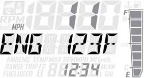
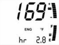
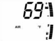
The Engine Program automatically displays the engine coolant temperature, engine hours, electrical system voltage level and fuel level (if equipped). On machines equipped with altimeter sensor and ambient air temperature sensors, altitude and ambient air temperature will display as additional screens in the engine program. Press the SET button to display the ambient air temperature and altitude screens. use the following procedures to make changes to these screens.
Hour meter: The hour meter records the total hours of engine operation since manufacture. This meter cannot be reset.
Engine temperature: A thermometer measures water temperature, giving an indication of engine temperature.
Air temperature (if equipped): The MFD displays actual air temperature in either standard or metric units.
1. Enter the Engine Program.
2. Press and hold the MODE switch for 10 seconds to switch between standard and metric units of measurement.
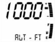
Altitude (if equipped): The rider can calibrate the altimeter for current atmospheric conditions. Altimeter accuracy will be +/- 300 feet (91 m) after adjustment.
1. Enter the Engine Program. Press and hold the MODE switch for 10 seconds to switch between standard and metric units of measurement. When "ALt" displays, the program is in the metric mode.
2. Press and release the SET button until the altimeter screen is active.
3. Press and hold the SET button for 5 seconds. When the digits begin to flash, release the button.
4. Press and release the SET button once to advance 50 feet (15 m). Tip: Press and hold the SET button to advance quickly by 100-foot (300 m) increments.
5. Adjust the altitude display to within 50 feet (15 m) of current altitude. Tip: The gauge reads barometric pressure and allows the rider to compensate for daily fluctuations in air pressure. The gauge can adjust the displayed altitude to +/- 1,300 feet (396 m) from the preset value. It will adjust up to +1,300 feet (396 m) above the calibrated altitude. once the +1,300 feet (396 m) offset has been reached, the next adjustment is -1,300 feet (396 m) from the calibrated altitude, and 50 feet (15 m) will be added to the altitude each time the SET button is pressed.
6. Press and release the MODE button to set the reading at the adjusted value. If the MODE button is not pressed within 10 seconds, the gauge automatically will save the new entry.
History Program: The History Program automatically displays electrical system voltage level and fuel level (if equipped).
While in the History mode, press the SET button to view maximum vehicle speed, maximum engine RPM or the current service interval setting. The gauge automatically logs the maximum speed and engine RPM even if the History Program is not currently displayed.
The History Program will display the history of the maximum speed, maximum RPM and service interval settings. To reset:
1. Enter the History Program.
2. Press and release the SET button until one of the two screens is active. Tip: The mph and RPM values are both reset at the same time. Reset the values before each run to obtain accurate readings.
3. Press and hold the SET button for 3 seconds to reset the recorded maximum values for both mph and RPM. Tip: Due to electrical noise, the MFD occasionally may display MAX MPH/RPM values that are not representative of actual values.
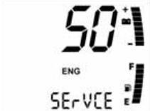
Service interval reminder: The gauge logs the number of engine hours accumulated between service reminders. When the logged hours reaches the designated service interval (set by the user), the gauge provides a reminder that service is due. "SErVCE" will flash in the odometer area and "ENG" will flash in the icon area for 5 seconds each time the engine is started (until the service reminder is reset). Use the following procedures to reset the reminder.
To reset the reminder at the existing interval:
1. Enter the History Program.
2. Press and release the SET button until the service interval screen is active.
3. Press and hold the SET button for 10 seconds, continuing to hold even after the display begins to flash.
4. When the display stops flashing, release the button. The service interval has been reset.
To reset the reminder at a new interval:
1. Enter the History Program.
2. Press and release the SET button until the service interval screen is active.
3. Press and hold the SET button for 5 seconds, until the hours begin to flash. Immediately release the button.
4. Press the button again, up to five times, to advance the reminder in 50-hour increments. Tip: The maximum interval is 250 hours.
5. Press and release the MODE button to save the new settings.
To disable the service interval reminder, press the SET button once after reaching 250 hours on the display. The gauge will display "OFF."
Battery replacement: Models equipped with the clock feature have a battery to power the clock. If the clock function of the MFD isn't working properly, replace the battery. Replacement batteries are available from your Polaris Dealer. To replace the battery:
1. Remove the plenum from the underside of the hood.
2. Locate the black battery compartment. It has a red wire and a brown wire with a white stripe. It's located about 3 inches down the main harness from the point where the harness connects to the MFD.
3. Cut the plastic cable tie from the outside of the compartment.
4. Carefully cut the bottom of the compartment (opposite the wires) to separate the heat-sealed seams. Squeeze the corners of the compartment inward so the battery is visible. Tip: Note the orientation of the battery before removing it. An incorrectly installed battery will not maintain the clock.
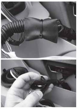
5. Using needle-nose pliers, grasp the battery and rotate it so the leading edge of the battery is raised away from the battery holder. Pull out the battery gently. Tip: The battery will not come out of the holder unless the leading edge of the battery is raised. Hold the battery compartment, not the wires, while removing the battery. Pulling on the wires will separate them from the battery holder.
6. Install a new battery with fingers only.
7. Seal the end of the battery compartment using high strength double-sided tape between the two compartment halves or high strength single-sided tape around the outside of the compartment.
8. Make sure the taped seam of the compartment faces the downward side of the wire harness.
9. Install a cable tie to secure the compartment to the wire harness in the same location where the previous cable tie was located. Make sure the battery wires are not stretched tight.
For more information on your instrument cluster along with other maintenance tips, procedures and specifications for your snowmobile, consult your Owner's Manual.
Note that certain products will damage the lens and other plastic surfaces. Do not use alcohol to clean the instrument cluster. Immediately clean off any gasoline that splashes on the instrument cluster.
For more information, see your authorized Polaris Dealer. To find a dealer near you, use the Dealer Locator.
Maintenance tips, procedures and specifications can be found in your Owner's Manual.
To find diagrams and replacement part numbers, use the online parts catalog.
Unless noted, trademarks are the property of Polaris Industries Inc.
© 2022 Polaris Industries Inc.

